A History of DIY Hi-Fi in the UK
Introduction
This paper charts the course of Do-It-Yourself hi-fi in the UK. Although a fair amount of detail is included, this is more a summary of the major developments rather than an exhaustive list of every project covered by the specialist press over the years. The aim is to give a flavour of how important this aspect of the hobby became, and in certain areas the contribution it has made to improvements in the reproduction of sound. The main focus is on British activities, but where appropriate reference is made to other countries when there is a link to what happened here.
Much of the paper’s content covers the period 1945 – 2000, because that was when DIY was part of the mainstream. In some ways this was the “golden age” for home-building equipment. However due regard has been paid to including references to earlier and later designs.
Since the invention of the first machines capable of recording sound, people have wanted to experiment with various techniques in an attempt to improve results. During the 1930s in particular there were several important technical developments and a notable focus on quality. The main limitation at that time was the calibre of source material, but various DIY projects were published which aimed to get the best out of what was available.
Post-World War II, the arrival of the microgroove vinyl record, and then FM Radio broadcasts begun by the BBC in 1955, resulted in huge improvements in the quality of source material available to British music-lovers, in terms of both extended audio bandwidth and signal-to-noise ratio. The advances in recording on magnetic tape made by the Germans during the War were also instrumental in significantly improving the quality of recorded sound post-war. Two-channel stereo had been proposed back in 1931 by Alan Blumlein of EMI, but its practical realisation on disc, tape and radio only became commercially available in Britain in the late 1950s/early 1960s. It was these developments which sparked a wider public interest in better sound reproduction in the latter part of the twentieth century, and consequent increased demand for suitable equipment to buy or to construct.
From about 1990 there was something of a decline in DIY projects published in the relevant magazines. Although Hi Fi World (begun in 1991) initially published a number of supplements dealing with DIY, it nowadays seldom includes such items. Hi Fi News likewise still published some constructional articles in the 1990s, but since the turn of the century the mainstream hi-fi press has largely ignored DIY. At the same time the electronics magazines aimed at the hobbyist, which often contained articles on audio projects, have mostly disappeared. There still exists a minority of enthusiasts who construct their own equipment, and there is plenty of information available on the Internet, but DIY Hi-Fi is nowadays a niche activity.
Why DIY?
A key driver for many hi-fi DIYers was the ability to save money. Even those with little technical knowledge or skill could successfully build a kit, which often performed as well as the equivalent commercial item and looked reasonably professional. Building from scratch required rather more knowledge, and simple metal-working or carpentry capabilities - but nothing much beyond those which many acquired as a result of the general post-war enthusiasm for DIY home improvement.
Another important aspect of DIY was the ability to experiment, and sometimes to exceed the performance of what was available commercially. There have been several instances where prototypes initially developed by enthusiasts have led to products which could be sold, and to the eventual establishment of a well-known brand. DIY also allowed customisation, by doing one’s own design or modifying the designs of others. This was of greater interest in the early days of hi-fi when there were far fewer products on offer and choice was limited.
Those who were not around at the time may be unaware and perhaps surprised to learn that in the early days there was also a certain snobbery attached to having built at least some of your hi-fi system. In some circles you were not regarded as one of The Initiated unless you could demonstrate you had the knowledge and ability to make something yourself, and thus maybe could go on to claim that your unique approach was better than anything else*.
|
*A 1960s skit on hi-fi by the popular entertainers Flanders and Swann contains a line which illustrates this nicely: “What? You bought it in a shop?! You’ve got wow on your top and flutter on your bottom.”
|
Finally, there have always been those who obtain great satisfaction from making something. Your home-made amplifier might be nothing special and look like a dog’s breakfast, but the fact that it worked and to your ears made music was reward enough.
Valve Power Amplifiers
The valve amplifier which is often cited as being of seminal importance was the design by D T N Williamson – of which more shortly. However there were notable attempts before WW2 to produce designs for quality amplifiers for home construction.
A good example of the latter was that published by W T Cocking in the 4th, 11th and 18th May 1934 editions of Wireless World. (In those days the magazine came out weekly; Mr Cocking subsequently became its Editor.) This was an all-triode design, with two directly heated PX4s operated in push-pull at the output stage, and no negative feedback (as such, it would doubtless appeal to a certain section of today’s hi-fi community). There was a separate “feeder unit” with a volume control and the first stage arranged as the phase splitter – what we would today describe as the pre-amp. On test, the unit was said to have a “distortionless” output of 4 watts, but up to 6 watts could be obtained. No figure was given for percent harmonic distortion, but a graph of input voltage versus watts out certainly shows a straight line up to 4 watts. Frequency response was quoted as just over 1dB down at 20 Hz, and 3dB down at 10kHz with the specified output transformer, which had been described with full constructional details in the issue of 8th Sept 1933. Mr Cocking ended by asserting that his amplifier “reached so high a standard that it is unlikely to be surpassed in the future”. He also suggested that since “the frequency response is practically perfect from 20 to 10,000 cycles… it is unlikely that an appreciably greater range will ever be needed for sound reproduction” - bold words indeed!
Another pre-war DIY “quality” amplifier worth mentioning is the design that was published in the four issues of Wireless World which came out in February 1938. Like Mr Cocking’s amplifier, full constructional details, diagrams and pictures were provided in the article to help the home constructor. This design was for those whose local mains electricity supply was still 200-250 volts DC – not an uncommon situation until AC mains became universal some time after WW2. The usual power supply arrangements for equipment to run off DC were applied: HT directly from the mains after suitable smoothing, and the valve heaters connected in series via a dropper resistor. But the amplifier itself was quite ambitious for its day, and the design is recognisably similar to many which appeared after the War. It used a “concertina” phase-splitter and a pair of indirectly heated, auto-biased KT31 beam tetrodes in push-pull for the output in order to produce enough power from the limited HT supply. Negative feedback* was applied to keep distortion low.
|
*
*A patent application covering feedback as a means of improving amplifier performance was filed in 1928 by Harold Black of Bell Labs in the US, and in 1934 he published a paper describing its use. However it does not seem to have been utilised very much until the late 1930s.
|
The specified output transformer was a commercially available item from Savage, with extensively sectionalised and interleaved windings. This, and the application of feedback, no doubt contributed to the remarkably good frequency response of the amplifier, which was only 0.7 dB down at 20Hz, and virtually flat up to 20kHz. The rated output of 5 Watts was considered ample at the time; moreover even at 20Hz some 4.5 Watts could be produced, and 4.8 Watts at 20kHz.
And so to the famous “Williamson”, which was first described in the April and May 1947 issues of Wireless World. In order to keep distortion to a minimum, the output stage used a pair of auto-biased, triode-connected KT66 beam tetrodes in push-pull. Mr Williamson did consider employing a pair of PX25s, which would have been capable of producing the 15 watts output he was aiming for. But like most other power triodes of the time, the PX25 was directly heated and had a 4volt filament which would have complicated the power supply and biasing arrangements. Mr Williamson noted that when triode connected the characteristics of the KT66 were very similar to the PX25; it was also indirectly heated and had the benefit of a 6.3 volt heater, both of which were then fast becoming the norm.
Mr Williamson used negative feedback over the whole amplifier, and was among those who recognised at an early stage the critical importance of the quality of the output transformer. In his articles he gives constructional details of a transformer rated at 20 watts, with 10 primary and 8 secondary windings, suitably interleaved. Measured by itself, this had a resonance well beyond the audible range at 60kHz, a slight lift of 1dB at 20kHz, and was only 0.5 dB down at 10Hz. The frequency response of the finished amplifier was within 0.2 dB from 10Hz to 20kHz, and total harmonic distortion at the rated output of 15 watts was found to be less than 0.1% at 400Hz. The output impedance was a desirably low 0.5 ohms, and signal to noise ratio 85dB.
In view of this excellent performance, the “Williamson” became very popular both as a DIY project and as several commercial products. Kits as well as
essential components were offered. For example, Partridge produced a very high quality output transformer at a cost of 6 guineas (roughly equivalent to £200 in today’s money – hi fi was never a cheap hobby).
Another DIY power amplifier dating from this period was a design by Peter Baxandall (of tone control fame) which appeared in the January 1948 issue of Wireless World. This used a pair of 6L6 beam tetrodes in push-pull, with overall negative feedback taken from a third winding on the output transformer as a means of improving the stability margin. Full constructional details were given of the special transformer needed. The driver/phase splitter circuit consisted of a pair of pentodes in a “paraphrase” arrangement (somewhat akin to that used later in Acoustical’s Quad II). Mr Baxandall’s amp had a rated output of 10 watts into15 ohms, flat to within 1dB from 30Hz to 16kHz, and with less than 0.1% harmonic distortion at mid frequencies. Presumably a good many of these amplifiers were built by enthusiasts, but the design does not seem to have attracted quite the same following as the “Williamson”.
The August 1949 issue of Wireless World carried an article by Mr Williamson giving further advice on his design, as well as some suggested minor modifications. These included an RC phase-shift network across the anode load resistor of the first valve, in order to improve the HF stability margin and to help prevent actual instability which some constructors had experienced. Also in 1949, the November issue of the American magazine Audio Engineering published an article by David Sarser and Melvin Sprinkle entitled the “Musician’s Amplifier”, which was acknowledged as being based on the Williamson, but using valves such as the 6SN7 and 807 which were more readily available in the US. Sarser and Sprinkle additionally advocated separating the amplifier and its power supply.
Another American modification to the Williamson was published in the June 1952 issue of Audio Engineering, by David Hafler and Herbert Keroes. As well as various changes intended to further improve stability margins, this included the substitution of an output transformer with “ultra-linear” taps. This resulted in a significantly greater power output of 25 watts while still retaining the benefit of low distortion typical from triode connected valves.
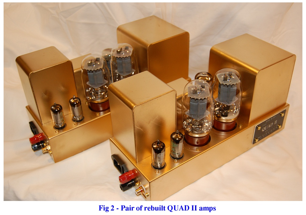
The ultra-linear connection was developed and patented by Alan Blumlein of EMI in 1937. However, like negative feedback, it was some time after its invention before it was used in commercial or DIY amplifier designs. In the September 1952 issue of Wireless World, an article by Mr Williamson and Peter Walker argued that rather than employing the ultra-linear connection, it was better to split the load on each output valve between the anode and cathode circuits. This was the approach used in the Quad amplifiers produced by Acoustical (as the firm was then known), of which the Quad II was a highly successful commercial design – some 90,000 units were manufactured between 1951 and 1970. Later, Acoustic Research and McIntosh in the US, and EAR in the UK also made amplifiers with this topology. But it never seems to have caught on with the DIY community, presumably due to the complexity and/or non-availability of the output transformer required.
The most significant British DIY valve amplifier designs to use the ultra-linear connection were those developed by the Mullard valve company’s engineers. Details of what became known as the “5-20” were published in articles by W A Ferguson in the May and June 1955 issues of Wireless World. An early version of the lower-powered “5-10” was briefly described in the August 1954 issue and featured in the Radio Show of that year. However this first 5-10 had the output valves pentode connected; a revised version, which included an ultra-linear output stage, came out in 1956.
The topologies of the 5-20 and the later version of the 5-10 were very similar. The first stage of both amps used the high gain/low hum EF86 pentode, which was directly coupled to the following ECC83 double triode driver/phase-splitter valve arranged as a “long tailed pair”. The EL84 output valves in the 5-10 produced just over 10 watts in ultra-linear mode, while the EL34s in the 5-20 readily exceeded the rated 20 watts over most of the audio bandwidth. Harmonic distortion for both amplifiers at their rated power output at mid-frequencies was 0.1% or less, but rose to higher levels at each end of the spectrum.
Like the “Williamson”, the two Mullard amplifiers proved immensely popular, and were fairly certainly the inspiration for if not the basis of some commercial designs. Many DIY kits were offered – such as those from Stern Radio - and several transformer manufacturers marketed products for those who wished to build from scratch. The Heathkit MA12 from this period appeared to be a derivative of the 5-10: while it used RC rather than direct coupling between the first and second stages and a larger rectifier valve, the circuitry was otherwise very similar.
Among the commercial designs which appear to have been based on the 5-20 was an early version of the Radford MA15. This had the same valve line-up, and pretty much the same circuitry as the 5-20, but with some minor changes aimed at improving stability. It was available as a fully built unit, or as a kit of parts. Radford also sold the transformers needed for scratch-building.
However, collaboration between Arthur Radford and Dr A R Bailey of the Bradford Institute of Technology resulted in a significantly new approach to the phase-splitter/driver stage of what became the Mark II version of the MA15. They noted that the frequency response of the first half of the ECC83 double triode used in the Mullard designs and in the Radford Mark I MA15 started to droop at about 3kHz due to the “Miller Effect” (feedback arising from anode to grid capacitance). By using a 6U8 pentode-triode valve instead, the frequency response of this stage was extended to 30kHz before it began to decline. This not only ensured that the open-loop gain of the amplifier was maintained at HF thus reducing top-end distortion, but it also improved stability margins consequent upon the phase shift resulting from the fall-off in frequency response being pushed out to beyond the audio band. Details of this approach to phase-splitter design were published by Dr Bailey in the September 1962 issue of Wireless World.
Radford and Bailey together published a series of articles in the June to September 1962 issues of Hi Fi News on the design and construction of the Mark II version of the MA15. As well as explaining the use of the 6U8 phase-splitter circuit, emphasis was placed not just on the quality of the output transformer but also on consistency in manufacture. Quite small variations in the physical layout and windings were found to affect the transformer’s characteristics quite significantly, such that the fine-tuning of the circuitry of the amplifier to compensate for transformer limitations was somewhat hit and miss. Radford therefore laid great stress on producing these components under very strict quality control and with minimal variation between individual transformers.
As well as the Mark II MA15, the 1962 articles in Hi Fi News also mentioned the STA15 stereo version which used a larger power supply to feed two amplifiers on one chassis. Additional reference was made to the MA25, which used much of the circuitry of the MA15 but had a rated power output of 25 watts, obtained by running the output valves with fixed bias and a higher HT voltage, and with a suitably revised output transformer. All these amplifiers were available as commercially built units, or as kits for the home constructor.
By the mid-1960s, the interest of amplifier constructors (and manufacturers) was shifting increasingly towards the use of transistors. However a new design for a valve amplifier was published by Dr Bailey in the December 1965 issue of Electronic Engineering. This was not really aimed at the DIY enthusiast, but it is worth including in this survey because it sported some novel features, and perhaps shows how valve amplifier design might have progressed if the transistor had not been invented.
Dr Bailey stuck to a pair of EL34s in ultra-linear push-pull for the output stage, and the basic layout of the rest of the amplifier was somewhat similar to the Radford designs. But he began by changing the input valve to an ECC88 double-triode in a “cascode” circuit to give high gain and low noise. For the long-tailed pair phase-splitter he used two EF184 frame-grid pentodes in order to ensure a good HF response, but with a relatively low value of 12k ohms for the anode loads so as to reduce their output impedance. This was aimed at ameliorating the problem of the high input capacitance of the output stage from loading down the drivers at HF. However the most radical change was in the feedback arrangements. At low frequencies feedback included the output transformer: a low pass filter was included in the path between the transformer secondary and the input valve. This was necessary to ensure the “iron loses” in the transformer at LF were adequately compensated for. But at HF, feedback was taken from the output valve anodes via a complementary high-pass filter, so as to avoid the problems of phase shift in the output transformer. Two such feedback paths were required, with a small transformer used to invert the phase from one anode so the feedback from both output valves was negative. This arrangement, designated “crossover feedback” by Dr Bailey, allowed the overall feedback to be increased to 40dB without causing stability problems. Moreover the feedback was effective over the whole audio spectrum. At the full rated output of 15 watts, harmonic distortion was less than 0.1% from 20Hz to 25kHz – a truly exceptional performance unmatched by few if any modern valve amps, most of which show large amounts of distortion at the frequency extremes.
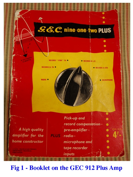 While the Williamson, the Mullard “Five Valve”, and Radford/Bailey designs were the most popular as DIY projects, there were several others to choose from. For example, not to be outdone by Mullard’s efforts to sell more of its valves, GEC also published constructional details of its 912 Amplifier - which of course used GEC’s valves and which had a rated output of 12 watts. The “912 Plus” which came out in 1956 was an integrated unit with comprehensive tone controls and, if required, a built-in pre-amp for a magnetic pick-up. In the April 1957 issue of Wireless World, W I Heath and G R Woodside published a design on behalf of GEC for a quality amplifier using KT88 output valves in ultra-linear push-pull, which could produce 50 watts at low distortion. Mullard also published an interesting design for a single-ended 3 watt amplifier, which aimed to get the best out of such circuitry principally through the use of a high quality output transformer and by employing a measure of negative feedback. Further Mullard designs included two stereo amps, one with ECL82s used in ultra-linear push-pull and the other with a single-ended ECL82 in each channel, and a 7 watt mono amp for use with AC or DC mains. Details of these were contained in the Mullard booklet “Circuits for Audio Amplifiers” published in 1959, along with the latest versions of the 5-10 and 5-20.
Interest in building valve amplifiers waned rapidly with the advent of transistor designs in the 1960s. The marked revival of interest in valve amplification, beginning in the late 1970s, and which continues to the present day, has been accommodated to a great extent by the provision of many commercial designs. But as late as 1993 Hi Fi World published an article and offered a kit to build the Mullard 5-20, and in 1994 Maplin Electronics offered its “Millenium” amplifier project based on the 5-20. A popular alternative for those with the necessary skills has been to refurbish old amplifiers from the 1950/60s, and there still remains a healthy market on ebay for Quad IIs, Leak Stereo 20s and Radford STA15s.
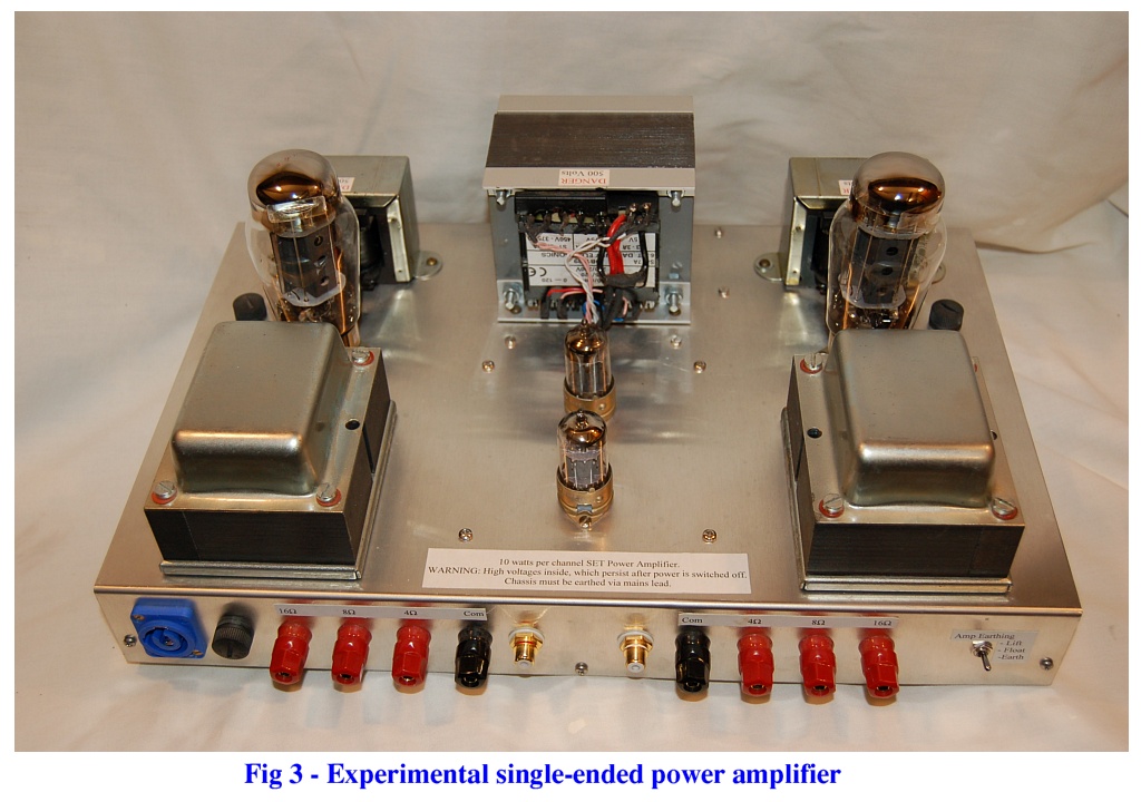
Although it has remained possible to acquire the necessary components or kits of parts for those who wish to build their own valve amplifier, this has become a minority activity and it is hard to point to any significant advances in DIY valve design since the1960s. Indeed, a trend among DIYers has been to revert to very early electronic circuitry in the form of single-ended, feedbackless amplification using long obsolete directly heated triodes. Partly because the designs for such amplifiers are so simple, no particular circuit can be cited as seminal. Also, their proponents are divided as to which is the most satisfactory approach: auto or fixed bias, solid state or valve rectification, old triodes or modern beam tetrodes strapped as triodes, RC or transformer inter-stage coupling, with feedback or none, using special (costly) passive components or not, and so on. At least it can be said that the experimental spirit is not dead.
Valve Pre-Amplifiers.
In the early days of hi fi, there was often little need for a separate pre-amplifier because the output from the available sources – radio tuner or gramophone pick-up – was sufficient to drive the power amp directly via a simple potentiometer volume control. The piezo-electric “crystal” pick-ups which were popular before and shortly after WW2 not only produced typically 500mV on recorded peaks, but also the better ones had a reasonably flat frequency response providing they were loaded with a high enough amplifier input impedance.
However there were several reasons why a pre-amp to drive an associated power amplifier became increasingly necessary. First was the development of much improved magnetic pick-up cartridges, having a low output and the requirement for significant equalisation – the latter tailored for the different characteristics of 78rpm and the various microgroove record standards which then pertained. Although piezo-electric pick-ups did not require as much gain or equalisation as magnetic types, it was nevertheless recognised that some attempt to flatten their response curve was worthwhile. There was also a demand for tone controls to boost or cut the bass and treble, and in more sophisticated equipment for filters specifically aimed at overcoming the defects of disc playback.
One of the early discussions of such matters is contained in a series of articles written by audio pioneer Paul Voigt in the February, March and April 1940 issues of Wireless World, on “Getting the Best from Records”. He considered the characteristics of different types of pick-up, and suggested some simple equalisation circuits to compensate for the shortcomings of both piezo-electric cartridges and the large and ungainly magnetic devices then used for playing 78s, which had replacable steel needles or freshly cut thorns. The articles included a design for variable bass and treble controls, but as Mr Voigt pointed out a bass “boost” in reality meant cutting the higher frequency response, so the losses in his passive circuit had to be recovered by another stage of amplification.
In the October 1952 issue of Wireless World, Peter Baxandall published what subsequently became his famous tone control circuit. This involved the use of frequency selective feedback around a single gain stage – preferably using a low-noise pentode valve. Mr Baxandall followed this up with a complete pre-amplifier in the January 1955 issue of Wireless World, which must rank as one of the most complex mono valve pre-amp designs. It used five valves (four EF86s and one EF80) and consisted of a three channel mixer, with one input at line level for radio or tape, one for magnetic or piezo-electric pick-up, and one for a microphone. The equalisation circuitry of the pick-up input catered for 78s and microgroove records, with a variable control for the treble roll-off on 78s to accommodate different recording characteristics. The microphone input had switches to adjust the gain, and to compensate for excessive bass when a ribbon mike was used close to the sound source. As well as full bass and treble cut and boost provided by his tone control circuit, Mr Baxandall also included a final stage with a high-pass “rumble filter”, and sharp cut-off “scratch filters” operating at 5 or 7.5kHz.
The July 1955 issue of Wireless World carried an article by D H W Busby of Mullard labs giving details of a three valve pre-amp using EF86s, intended for use with the 5-20 power amplifier. The first stage provided gain and equalisation by frequency selective feedback for 78s and microgroove records, with both magnetic and piezo-electric pick-ups being catered for. The input selector switch also had positions to accommodate a microphone and a radio tuner. The second stage provided gain to compensate for the losses in the passive tone controls which followed, while the third stage was based on the high and low pass filter circuits around the final valve in Mr Baxandall’s elaborate pre-amp.
For the 5-10 power amplifier, Mullard noted that with a very high input sensitivity of 40mV in for 10 watts out it was possible to incorporate passive bass, treble and volume controls at the input yet still have sufficient sensitivity for use with a radio tuner or piezo-electric pick-up. However if it was desired to use a magnetic pick-up with the 5-10, then Mullard gave details in one of its publications for a simple one valve pre-amp to provide the necessary additional gain and equalisation, prior to the passive tone controls.
In May 1957 Mr Baxandall published a circuit for a far simpler pre-amplifier than his earlier design, again using his feedback tone control circuitry but with inputs for just radio and a piezo-electric pick-up. This used a single ECC83 double triode. As well as compensating separately for 78 and microgroove records to give the flattest response, there were further positions on the input selector switch for “old” records of both types, which incorporated a fixed treble cut intended to ameliorate the sound from worn discs.
Mullard’s 1959 publication “Circuits for Audio Amplifiers” contained designs for three pre-amps. The first used two EF86 valves and was very similar to Mr Busby’s earlier, 1955, design intended for the 5-20 power amplifier, but without the final filter stage. There was also a stereo pre-amp based on this two valve mono design, but with two channels and suitable balance and mono/stereo switching controls incorporated. The third pre-amp was another mono design using three valves – two EF86s for the first stages and one ECC83 for the output and filter circuits. The latter were rather more comprehensive than those in the 1955 design: the high-pass rumble filter could be switched between corner frequencies of 20, 40, 80 and 160Hz, while the low-pass scratch filter used an inductor in a “pi” circuit and was switchable between cut-offs of 5, 7, and 9kHz as well as a nominally “flat” position. A period feature of all these pre-amps was provision for an input directly from the playback head of a tape transport, with adequate gain and CCIR equalisation. This was intended for the reproduction of commercially available pre-recorded reel-to-reel tapes such as EMIs “Stereosonic” recordings, which made their brief appearance at about this time.
Following the articles on the MA15 power amplifier which appeared in 1962, Arthur Radford subsequently published two designs in Hi Fi News for pre-amps to go with it. Although these were commercially available products, Mr Radford generously gave full details of the circuitry and tips on construction. A particular departure from the earlier designs cited above was the use of ECC83 double triodes in the sensitive first stage circuits, rather than EF86 pentodes. Mr Radford’s research showed that lower noise could be obtained by using the first half of the ECC83 as a straight gain stage and buffer for the magnetic pick-up input, before the signal was fed to the second half carrying the RIAA equalisation circuitry. Another notable difference from earlier pre-amps was the use of a cathode follower output to avoid losses arising from long leads between the pre and power amplifiers. As a sign of the times, the Radford pre-amps eschewed provision for 78 records and did not cater for direct input from a tape-head. An efficient high-pass filter was still included, not just to cope with turntable rumble but also to remove frequencies below 35Hz which, Mr Radford pointed out, could cause problems. He also argued that a simple treble roll-off filter was better for dealing with record imperfections rather than the steep-cut filters then thought desirable.
From the mid-1960s onwards, few valve pre-amp designs appeared as interest focussed increasingly on transistor circuits. In addition, it became fashionable in the 1970s not to include amplifier tone controls or filters, and once CDs arrived in 1982 there was no requirement for the high gain and equalisation required by magnetic gramophone pick-ups, assuming vinyl record playing was abandoned in favour of the new digital medium. A simple input selector switch and volume control built into the power amp was often considered quite adequate, without any need for a pre-amp.
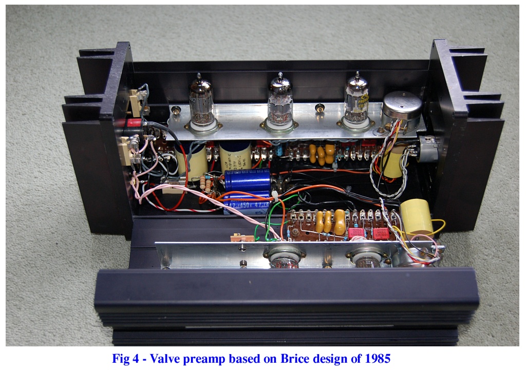
However there were some DIY valve pre-amp designs produced latterly which included provision for vinyl record reproduction. One of the more interesting and innovative circuits was that published by Richard Brice in the June 1985 issue of Wireless World. In his 1962 articles on pre-amps for the MA15, Arthur Radford had noted that the lowest noise input he had been able to obtain was with an ECC82 double triode operated as a cascode stage, and with a DC heater supply. This was never used by Mr Radford in his commercial products as being too uneconomic; however it was utilised by Mr Brice to good effect in his 1985 design. Mr Brice used a passive RIAA equalisation network rather than one involving frequency selective feedback around a gain stage. In order to feed this from a suitably low impedance source, he interposed a cathode follower between the high impedance output from the ECC82 cascode and the network. The losses from the RIAA equaliser were made up with a gain stage consisting of one half of an ECC83, after which there was a volume control and another cathode follower to provide a relatively low impedance output. Mr Brice’s circuit appeared again in the February and April 1993 issues of Hi-fi World, together with some suggested modifications.
Before leaving the subject of valve pre-amplifiers, it is worth noting that most of them were constructed in an enclosure separate from their associated power amplifier. This allowed the heavy and heat-producing power unit to be placed in a position where it could receive adequate ventilation, while the pre-amp was sited for convenient access to the controls. Furthermore, the sensitive input circuits could thus be kept well away from sources of interference, such as hum induced by too close a proximity to a mains transformer. HT and LT power supplies for the pre-amp usually came from the power amplifier as a matter of economy.
Transistor Power Amplifiers.
In the September 1956 issue of the American magazine Electronics there appeared an article by H C Lin of RCA Laboratories giving details of a “Quasi- Complementary Transistor Amplifier”. This had a rated output of 6 watts at 400Hz with less than 1% distortion, and some of the devices used were “experimental”, so presumably they were not commercially available. Nevertheless this was a seminal design in that it showed how a transistor amplifier could be made without the need for transformer interstage coupling, and how to use complementary pnp and npn driver transistors to feed a pair of pnp (or npn) output devices. Ideally a Class B amplifier of this type should employ complementary output transistors as well as drivers, but it was some time before such devices became available, and even when they did appear they were initially very expensive. So elements of Mr Lin’s circuitry were much in evidence in early transistor amplifiers – both DIY and commercial designs.
The first UK design for a transistorised power amplifier with sufficient capabilities to be given serious consideration for use in a hi fi system was that published in the November 1961 issue of Wireless World by R. Tobey and J. Dinsdale. This used germanium devices and followed the Lin topology with some additions: an extra gain stage was included in the feedback loop; a forward biased diode rather than a thermistor was used for temperature compensation; and small value resistors were included in the output transistor emitters. This power amp could produce 10 watts into a 15 ohm load, with 0.25% total harmonic distortion at mid frequencies. Overall frequency response was given as being within + 1dB from 40Hz to 20kHz, with the possibility of extending the low frequency response by increasing the size of the output capacitor. As well as being a popular DIY project, the Tobey and Dinsdale design was also featured in commercial products such as the Leak Stereo 30 – one of the earliest British transistor amplifiers.
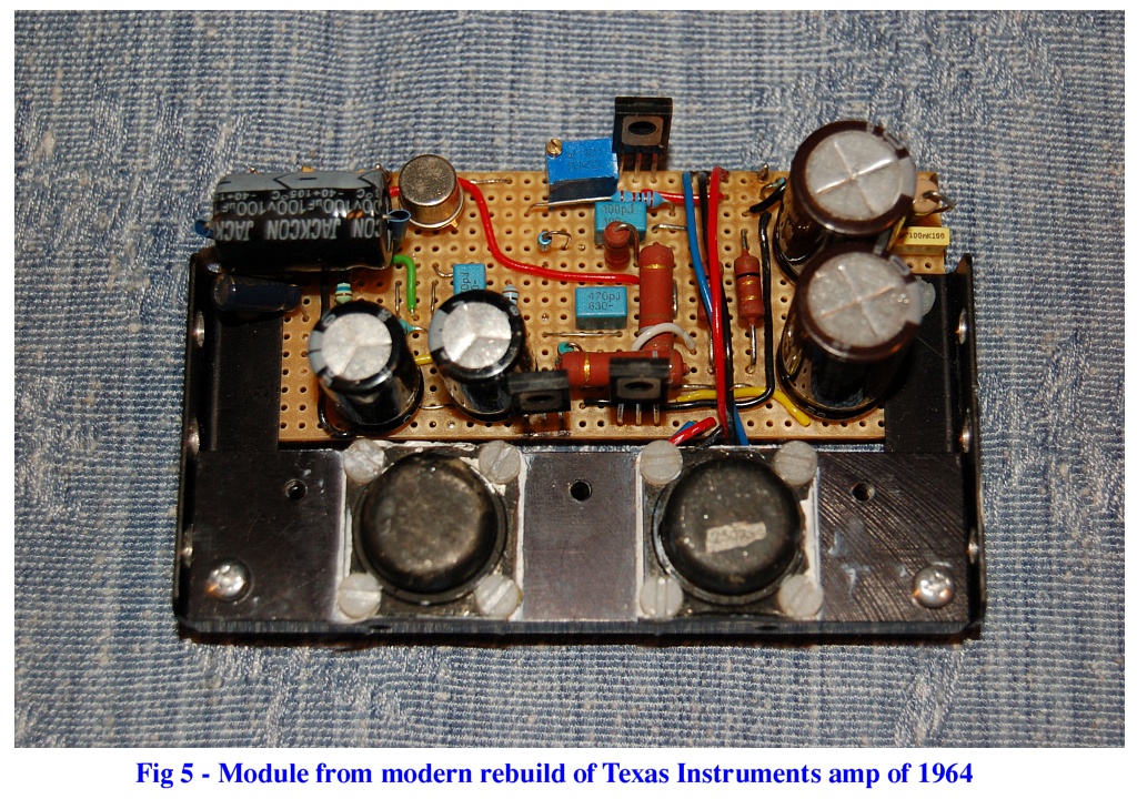
There followed many similar designs, one of which was an interesting circuit by Texas Instruments which was published in the April 1964 issue of Hi Fi News, as part of a review of transistor amplifier design by L N Hulley of the Bradford Institute of Technology. The basic layout was that of a Class B quasi-complementary amplifier in the Lin/Tobey and Dinsdale mould; however it used very fast 2SO26 silicon output transistors, as well as silicon devices in the rest of the circuit. There was a simple regulated power supply, to prevent the supply rail voltage from drooping under heavy load while at the same time ensuring the breakdown voltage of the transistors was not exceeded in quiescent conditions.
The measured performance of this amplifier by Texas Instruments was quite exceptional for the time. It could produce 30 watts into an 8 ohm load with only a drop of 1dB at 8Hz and 100kHz. Harmonic distortion was less than 0.1% over most of the audio spectrum, rising to 0.2% at 50Hz and 20kHz. There were some issues with stability into capacitative loads, but no more so than with many other transistor amplifiers. The design showed what was possible, but it was never destined for widespread use by DIY constructors or for commercial application due to the extremely high cost of the output devices.
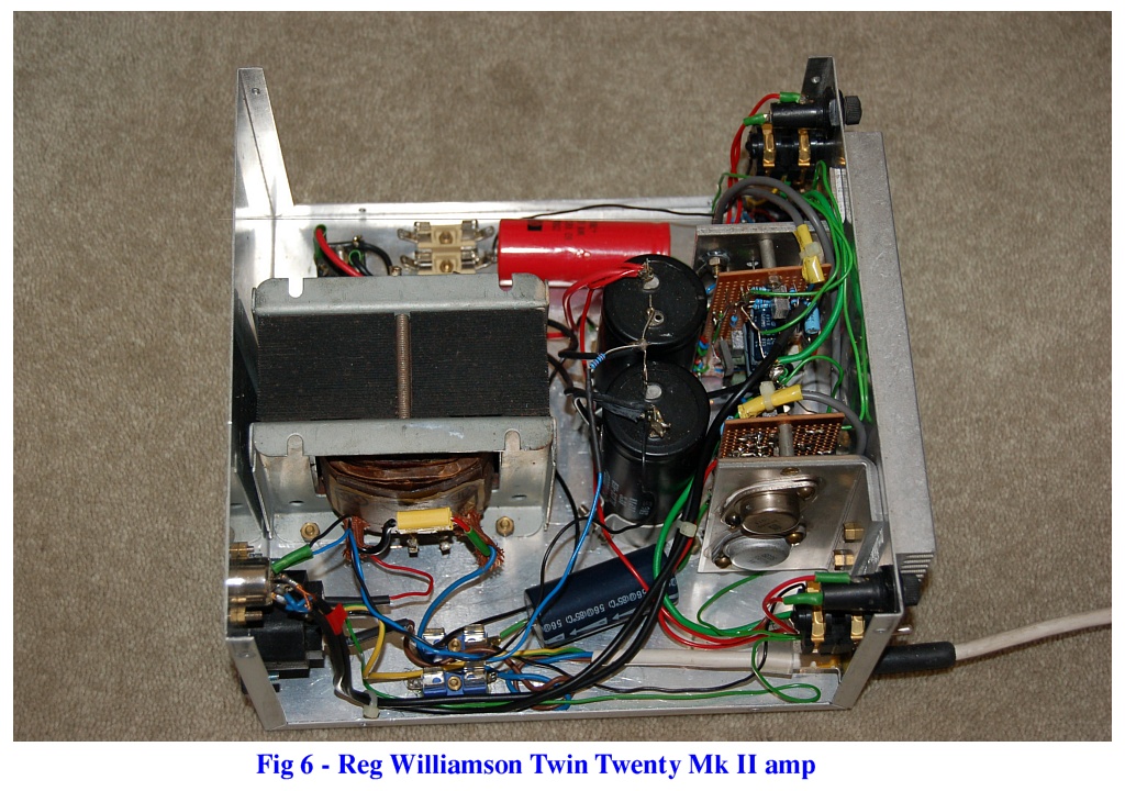
During the 1960s a more practical proposition was the circuit of the “Twin Twenty” amplifier published in the August 1967 issue of Hi-Fi News. The design was by Reginald Williamson (no relation of D T N Williamson of valve amp fame), and it used silicon transistors throughout. The topology was similar to that of the Tobey and Dinsdale circuit, but with resistors (and for the pnp driver, a diode also) in series with the inputs to the output stages as a means of mitigating the effects of the asymmetry inherent in quasi complementary designs. The power supply included fast-acting protection. Full constructional details were given as was usual at the time.
The original Twin Twenty amplifier was capable of producing 20 watts per channel into a 15 ohm load, with distortion of less than 0.1% from 30Hz to 6kHz, rising to 0.35% at 20kHz. It was evidently popular as Mr Williamson subsequently published a Mark II version using a full complementary output stage in the March 1969 issue of Hi Fi News, and a further update in the September and October 1971 issues. The later versions boasted significantly lower levels of distortion.
An early design with a fully complementary output stage was that published by Dr Arthur Bailey in the May 1968 issue of Wireless World. This could produce 30 watts into an 8 ohm load with less than 0.1% distortion over the whole audio spectrum: consequently Dr Bailey wondered if transistor amplifier design had much further to go. His amplifier was also one of the first to use a split-rail power supply, thus eliminating the large output capacitor which had been the norm up to this point.
A design by Barry Goldsmith published in the October and November 1969 issues of Hi Fi News used a quasi-complementary output stage, but was notable as being one of the first to use a long-tailed pair of transistors at the input. In the July and August 1970 issues of Hi Fi News Ian Hardcastle and Basil Lane published generic circuits for a “family” of power amplifiers with different outputs. These had fully complementary output stages as well as long-tailed pairs at the input. Another design from this time was that published in the December 1970 and February 1971 issues of Hi fi News by G A Stevens of Solartron Laboratories. This was notable for the use of output transistor “triples” in the quasi-complementary topology it employed.
By the late 1960s some enthusiasts were beginning to question the sound quality of transistor amplifiers, despite their - by then - good measured performance. It was suggested that the use of Class B output circuitry was to blame and that it would be better to use Class A, despite the inefficiency and inevitable heat generation which such designs would entail. Among the Class A amplifiers offered for home construction was that published by John Linsley-Hood in the April 1969 issue of Wireless World. This was followed in the March 1970 issue with a design by L Nelson-Jones. Then in the April and May 1970 issues of Hi Fi News, James Sugden published a circuit and constructional details for a Class A amplifier based on a commercial design sold by his company. As expected, all these amplifiers exhibited the desired low distortion at low as well as higher levels of output, but their main limitation was with the maximum power available being of the order of 10 watts.
Another popular DIY design was that published by John Linsley-Hood in the November and December 1972 issues of Hi Fi News. This used a quasi-complementary Class B output stage, and could produce up to 75 watts per channel into an 8_ load at no more than 0.01% distortion. It was directly coupled, and employed a diode and capacitor connected between the emitter of the pnp driver transistor and collector of its associated npn output device in an arrangement which – as Mr Linsley-Hood acknowledged - had been suggested by Peter Baxandall as a means of improving the performance of quasi-complementary output circuits. Oscillograms showed how crossover artifacts were apparently eliminated by this means. A kit of parts subsequently became available to build the amplifier, and Mr Linsley-Hood published follow-up articles in the May 1973 and April 1974 issues of Hi Fi News.
Mr Linsley-Hood published another amplifier design in the January, February and March 1980 issues of Hi Fi News. This had a rated power output of 30 watts at low levels of distortion, and was notable for its use of complementary “Darlington” transistors in the output stage. A kit to build this was offered by Hart Electronics. Later (December 1980) Mr Linsley-Hood published a revised version of this circuit with MOSFET output devices, and in the June and July 1984 issues of Electronics Today International (ETI) there appeared a further design by Mr Linsley-Hood with paralleled MOSFETs in the output. This design was capable of producing 80 watts per channel at very low levels of distortion, and in due course this also became available as a kit.
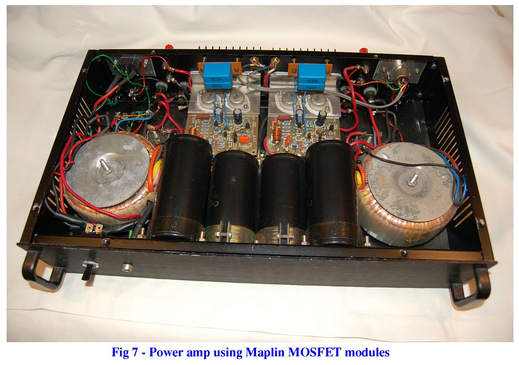
Another MOSFET-based power amplifier for home constructors from this time (mid 1980s) was the Maplin module, designed by Dave Goodman. It could be purchased ready assembled or as a kit of parts, and only required the addition of a simple power supply. Output was given as 50 watts into an 8 ohm load or 75 watts into 4 ohms, and distortion of less than 0.005% over the full audio bandwidth. More power could be obtained by adding further output devices in parallel. This kit was Maplin’s top seller, which again illustrates the very high level of interest in DIY still pertaining at the time.
Many other DIY amplifier designs were published in the 1980s, and some during the 1990s. But by this time interest in home construction was seemingly waning. One of the last articles to appear in Hi Fi News on amplifier construction was a brief review of a kit in the February 2003 issue, but that was a rarity. It remained, and indeed remains possible to obtain the parts needed to build a transistor amp but this is certainly no longer part of the mainstream. For those who wish to build a solid-state amp, there are now available several complete, inexpensive amplifier-on-a-chip I/Cs with really quite an acceptable performance. For example, the Texas Instruments LM3886 is capable of producing 50 watts at 0.02% distortion mid-band with just a simple power supply and a few external components.
Transistor Pre-amplifiers
Whenever a new design for a power amplifier was published, often a circuit for a matching pre-amplifier would be published, too. There were inevitable variations in the precise topologies employed, but in the 1960s and 70s it was usual for all the facilities then expected by enthusiasts to be incorporated. The front end would typically consist of a pair of transistors with a frequency selective RIAA feedback loop round them to meet the needs of a moving magnet pick-up. Then there would follow another gain stage with bass, treble, volume and balance controls, and often rumble and variable slope scratch filters. Finally an emitter-follower buffer might be added to provide a low impedance output.
The performance of these earlier circuits was satisfactory by the standards of the time, with low noise and distortion, and a wide frequency response. The main drawback was that with the far lower supply voltage used for transistors compared with that used with valves, there was a greater risk of overload from excessive output from the pick-up when playing “hot-cut” records. Subsequent designs took greater account of this, with care being taken to ensure the gain architecture was suitable, and sometimes using a higher supply voltage for the front end to increase the dynamic range.
Examples of transistorised DIY pre-amp designs include:
- Wireless World, Dec 1961, for the Tobey and Dinsdale amp.
- Hi Fi News May 1967, for the Williamson “Twin Twenty”.
- Hi Fi News Aug 1969, for the Williamson Twin Twenty Mark 2.
- Hi Fi News Nov 1969, for the Goldsmith amp.
- Hi Fi News Oct 1970, for the Hardcastle and Lane amps.
- Hi Fi News Sep 1971, revision to pre-amp for Williamson Twin Twenty.
- Hi Fi News Jan 1973, for the Linsley-Hood 75 watt directly coupled amp.
- Hi Fi News Feb 1980, for the Linsley-Hood 30 watt amp.
The performance of the earliest op-amp I/Cs was usually regarded as inadequate for use in high quality pre-amps. Mr Linsley-Hood went so far as to design a high quality gain-cell which he called the “Liniac”, consisting of several discrete components, but it was some time before he incorporated any single-chip devices in his circuits. However, one of the first DIY designs to use an I/C was that for a phono pre-amp by Mr Linsley-Hood in the March 1977 issue of Hi Fi News, which employed a low noise version of the National Semiconductor LM381. And in the pre-amp for his 30 watt amplifier published in the February 1980 issue he used a 741 op-amp for the output stage.
By the early 1980s a better range of I/C op-amps became available, and in consequence they featured in several DIY pre-amp designs. For example, an article in the October 1983 issue of Wireless World by D Self described a pre-amplifier which used the low noise NE5534A op-amp chip throughout. This incorporated a magnetic pick-up input stage with a high-pass rumble filter and RIAA equalisation. Bass and treble tone controls were also included, while the volume control was of the active feedback type rather than a simple potentiometer.
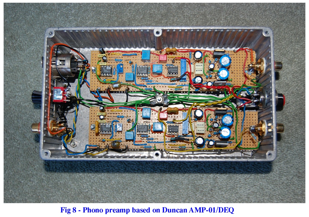
An alternative approach was provided by the “AMP-01” modular pre-amplifier by Ben Duncan, published in the May to October 1984 issues of Hi Fi News. This used a variety of I/C op-amps, and could be configured in several ways to suit the wishes of the builder. With this purist design, tone controls and filters were eschewed, and much emphasis was placed on component quality. Provision was made for moving coil as well as moving magnet pick-ups in the phono section, including the option of using the differential input of the first device in a quasi-balanced arrangement in order to keep hum and noise to a minimum when using a moving coil cartridge.
In the October and November 1989 issues of Hi Fi News Mr Duncan published an updated version of his pre-amp, using the latest audio I/Cs. This included a very low noise device intended for use as a microphone pre-amplifier, but in this case employed as the first stage of a fully balanced input to the moving-coil pick-up module.
Loudspeakers
Just as popular as amplifier-building was the construction of loudspeakers – or rather the cabinets, horns or other structures used to contain the loudspeaker chassis, and the crossover networks where these were needed. Although there were some people who experimented with making the drive unit itself, they were mainly those who aimed to make such things commercially. While books were written on the theory and construction of exotica such as ribbon and electrostatic loudspeakers, the average DIYer was happy to buy the ready-made moving coil chassis or chasses he or she required.
In the 1930s, the norm when aiming for quality of reproduction was either to mount the drive unit or units on a baffle-board, or to use a horn. For baffle-mounted speakers there was recognition that using a large moving coil unit to produce the lower part of the audio spectrum, crossing over to something better able to handle higher frequencies, was a useful approach to improved reproduction (the term “tweeter” was already in use by then for such devices). The latter could be simply a smaller moving coil unit, or perhaps a piezo-electric device, while in the 15th and 22nd September 1933 issues of Wireless World, M G Scroggie (famous for his seminal book “The Foundations of Wireless”) wrote about “The Electrostatic Loudspeaker”, and suggested the technology was particularly suited to the reproduction of high frequencies.
Horns were of particular interest pre-war because of their high efficiency and the limited power available from the amplifiers of the period. But there were considerable difficulties to be overcome when it came to quality reproduction in a domestic environment. These were addressed in the pioneering work of Paul Voigt: the performance of his Domestic Corner Horn of 1934 was a revelation, and it is fair to say that it eclipsed pretty well everything else at the time. Mr Voigt paid great attention to the contours of the horn so as to minimise coloration, and by the use of a bass chamber and siting the speaker in the corner of the room so the walls acted as an extension of the horn, he was able to get a good low frequency response from a cabinet of acceptable dimensions in the home. The design of his drive unit was also crucial to the excellence of the performance of the Domestic Corner Horn. Mr Voigt used a small, lightweight paper cone and a powerful electromagnet to give high sensitivity, good damping, and a good transient response. Later he added a second cone inside the original one to extend the high frequency response, which went up to 12kHz. While the Domestic Corner Horn was sold as a commercial product, details were also given for the DIY construction of a horn to suit the Voigt drive unit.
Pre-war loudspeakers often used an electromagnet to provide the magnetic field needed. In this case, DC for the field winding was usually obtained by wiring the winding in series with the HT supply to the amplifier, where it also helpfully functioned as a smoothing choke. Permanent magnets of the period were of limited strength. However the development of powerful permanent magnets during the War for use in radar tubes allowed the development of better loudspeaker drive units post-war. Other improvements resulted from changes to the cone surround and suspension, and in some cases to the cone material (eg the GEC Metal Cone loudspeaker, and the WB Stentorian cone of stiffened Cambric).
A seminal work which focussed particularly on how to get the best from the new drive units was the book simply titled “Loudspeakers” written by Gilbert Briggs of Wharfedale. This was first published in 1948, and went through several revised editions in the following decade. At the time it was the “Bible” for DIYers, who were able to design and construct an enclosure to suit their particular needs with relative ease. Although Paul Voigt had shown how to get good results from a horn, construction of such enclosures was complex for the amateur. And with the higher powered quality amplifiers which became available, there was less of a requirement for great efficiency on the part of the loudspeaker. So was born the age of the bass reflex cabinet, with a separate driver or drivers for the mid and treble – a recipe for speaker design which still finds favour to the present day. Mr Briggs’ book covered not just the theory but also constructional details of various types of enclosure, including horns, open baffles, transmission-lines, and closed boxes; but the most popular of his designs were those based on the reflex principle. As well as wooden cabinets – perhaps using a filling of dry sand between a sandwich of plywood boards – Mr Briggs also showed how a corner enclosure could be built of bricks in order to minimise cabinet coloration. Later suggestions were to use a concrete drainpipe or an old beer-barrel as reflex enclosures, with a single 8 inch full-range driver facing upwards. Such inexpensive and space-saving solutions were particularly popular in the early days of stereo, with its requirement for two loudspeakers.
One of the best tweeters of the late 1950s /early 1960s was the ribbon unit produced by Stanley Kelly. This had a far smoother and more extended response than most others of the period. An impressive performance could be obtained from a DIY speaker system using a Kelly Ribbon, with a 15 inch bass unit in one of Mr Briggs’ reflex designs, and an 8 inch driver mounted on a small baffle for the mid. However the Kelly Ribbon was quite expensive, and it was fragile. A popular and cheaper alternative of the time was the TSL Lorentz tweeter, which was a conventional moving coil design, but with a small, lightweight plastic cone. Even the BBC indulged in a bit of DIY with this: when FM broadcasting began in 1955 their existing monitor loudspeakers were incapable of producing much above 4 or 5 kHz, so as a stop-gap measure they attached a TSL Lorentz unit to the centre of the expanded metal grille of the monitor, fed via a suitable capacitor.
As well as Mr Briggs’ book, another seminal work was the article published by Arthur Bailey in the October 1965 issue of Wireless World, which explained the advantages of using a transmission-line enclosure for the bass, with long-fibre wool as the acoustic absorbing material. Construction details of a complete loudspeaker were given by Dr Bailey, using a KEF B139 driver for the mid-bass, and a Celestion HF 1300 tweeter for the treble. Many DIY and commercial designs followed based on Dr Bailey’s research; for example, in the June 1972 issue of Hi Fi News Jim Mathers gave details of a transmission line loudspeaker for home construction.
During the 1960s, and continuing into the 1970s and 80s, a great many DIY speaker designs were published in the hi-fi press. Some of these were quite elaborate: for example L R Frisby’s “No Compromise Loudspeaker” published in the February 1974 issue of Hi Fi News: this used four drivers per side and a concrete-lined cabinet. Another design which aimed high was the “State of the Art Loudspeaker” in the April 1976 issue of Hi Fi News, which used six drivers per side. For the really ambitious, details of how to build large folded horns into the structure of one’s house were given; for example by John Crabbe (Hi Fi News, Nov 1961-June 1962, and again in October-November 1967) and by Colin Walker (Hi Fi News, September 1969 and March 1980).
Constructional details were also given of several much more modest and inexpensive designs. For example, in the August 1968 issue of Wireless World Peter Baxandall described a small, low cost loudspeaker using a single elliptical driver in a closed-box enclosure. A novel feature of this was the use of a passive equalisation network to compensate for the main deviations in frequency response of the particular driver he chose. By this means Mr Baxandall was able to achieve a remarkably good performance –above 100Hz, at least. In the September issue he therefore outlined various ways of adding a suitably inexpensive sub-woofer to extend the low-frequency coverage of the system. This was one of the first satellite-plus-sub systems, which subsequently became very popular with DIYers and manufacturers alike. In due course a kit was made available for those wishing to construct Mr Baxandall’s speakers.
Some of the other low-cost DIY designs which appeared in Hi Fi News were based on the quarter-wave pipe principle pioneered by Paul Voigt, with a full-range single driver, such as the “Paraline” by Rex Baldock and the “Posthorn” by Sir John Holder (December 1972). Examples of low-to-medium cost bass reflex or closed-box designs included S Hutton’s “Inexpensive Reflex Speaker” (December 1971), “Three Readers’ Home Built Designs” (December 1976), the “Tabor” (September 1977), the “Deccavolt” and the “Meister II” (both November 1982), and “Son of Meister” (May 1983).
As well as full-range speakers, a good many DIY designs were published for sub-woofers. A particularly popular one was Trevor Attewell’s “Basset”, the original version of which appeared in the April 1969 issue of Hi Fi News, with revised versions coming out in June/July 1978, and in May 1986. A later example was the “Monochord” DIY sub-woofer by Richard Lord, published in the February 1991 issue of Hi Fi News. Mr Lord subsequently went on to become a noted manufacturer of sub-woofers. Details of suitable crossover circuits were usually included with instructions on how to build the sub-woofer itself.
To give some idea of the popularity of speaker-building in its heyday, a Wilmslow Audio advert which ran in Hi Fi News in 1980, listed 61 individual drivers and crossovers, 38 kits from 10 manufacturers to enable the construction of loudspeakers nominally the same as their commercially available units, and 17 kits for various DIY designs which had appeared in the hi fi press.
During the 1990s a few further designs appeared, such as a three-way speaker with a ribbon tweeter in the Supplement to the June 1993 issue of Hi Fi World, and an active dipole sub-woofer in the Supplement to the April 1996 issue. Hi Fi News published a design called the U-line in October 1992, and reviewed the Wilmslow Audio sub-woofer kit in the May 1993 issue. Later designs in Hi Fi News included the DBS7 and 8 in the September 1997 and October 1998 issues respectively.
Although there appear to have been few if any DIY designs published after the turn of the century, speaker-building evidently still appeals to some to judge from Wilmslow Audio’s and IPL Acoustic’s continued existence. Another firm specialising in supplying the DIY loudspeaker market, still trading, is Falcon Acoustics who specialise in supplying kits and components to build small two-way speakers which emulate the famous LS3/5A BBC design. However Badger Sound Services, which used to be another prominent supplier, is no longer in existence.
Turntables and pick-ups
Until the arrival of the Compact Disc – and to a lesser extent the Compact Cassette - the gramophone record was the major source of recorded music for most people. Even to the present day it remains the source of choice for some enthusiasts. However construction of one’s own record playing equipment was seldom an option for the vast majority of music lovers, in the way that amplifier and speaker building had been. Not only was considerable knowledge of and skill in precision engineering required, but one also had to have access to a workshop with the necessary high quality machinery. Of course there were a few who had both, such as Alastair Robertson-Aikman of SME, who initially designed and built a pick-up arm for his own use, being dissatisfied with what was then commercially available. Thereafter his company became a leading manufacturer of pick-up arms - and later turntables - of the highest quality, initially designed to fulfil Mr Robertson-Aikman’s personal requirements.
At a less exalted level there were some DIYers who managed to make their record playing equipment. For example, there was the Connoisseur BD1 turntable kit, and occasionally articles appeared describing how someone had built their own turntable from scratch, eg by Paul Chappell in the July 1997 issue of Hi Fi News. In the January and February 1966 issues of Wireless World, Jack Bickerstaffe gave the background to and full constructional details of a unipivot pick-up arm he had designed.
However, for most people there was little choice but to buy a finished turntable, arm and cartridge, separately or as a package. Despite this, those wishing to effect improvements had plenty of opportunities to do so via various after-market modifications, such as different turntable mats, motor upgrades, improved motor power supplies, alternative arm counterweights, and arm re-wiring. There were articles on building a mains regenerator to power an AC turntable motor in the June 1973 and March 1998 issues of Hi Fi News.
Tape recorders
A desirable addition to one’s system in the early days of hi fi was a reel-to-reel tape machine. This afforded the possibility of carrying out live recording, especially in view of the availability at the time of good quality ribbon microphones at reasonable cost. However the greater value for most music lovers was the ability to record radio programmes – either for time-shifting purposes, or to listen again to what had been broadcast.
The term “tape recorder” was generally used for machines which had a built-in amplifier and loudspeaker for playback. However the latter facilities were not needed if the recorder was to form part of a hi-fi system, in which case the electronics could be simplified somewhat and the speaker omitted: such machines were usually called “tape decks”. Unfortunately the same terminology was also used for the electro-mechanical tape handling system which could be acquired by those wishing to build their own electronics: for the sake of clarity this paper will use the term “tape transport” to describe that part of the machine.
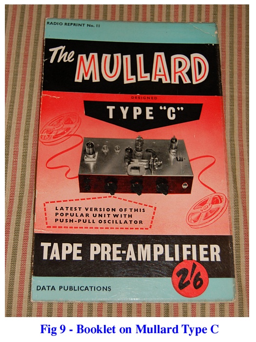
As was the case with record-playing equipment, there were very few people who possessed the skills, knowledge and facilities to design and build their own tape transport. However the construction of one’s own electronics to go with one of the several (British) tape transports available in the 1950s and 60s was a means of acquiring high quality tape recording facilities at reasonable cost. Probably the most popular circuits were those published by Mullard from the mid-1950s onwards. Their “Type A” unit included switching around an EL84 pentode to change it from being the bias oscillator during record to the output valve of a small amplifier on playback, so that with a suitable transport it made a complete recorder. The “Type B” electronics omitted the switchover around the EL84, so with a transport was intended to provide tape facilities for use with a hi-fi system – ie a tape deck. Later, the “Type C” circuit was published, which was an upgrade on the Type B. This had a push-pull bias oscillator driven by an ECC82 double triode, which through its better waveform was intended to improve the signal-to-noise ratio. The Type C also used an LCR circuit for better control of record treble boost, compared with the RC “twin T” networks used in the early Type A and B electronics.
Due to the different characteristics of the record and erase heads on the various commercially available tape transports, instructions were given in the Mullard manuals on the coupling capacitor to be employed for the bias feed, and which tap on the oscillator coil secondary was required for the erase head. No less than six tape transports were cited in this guidance for the Type C circuit: these were produced by Brenell, Wearite (Ferrograph), Lane, Motek, Truvox and Collaro. A further measure of just how popular these Mullard designs were is shown by the adverts from five different companies for kits to build the Type C in a booklet reprinted from the original articles which had appeared in The Radio Constructor magazine, as well as in Mullard’s own publications.
The Mullard 1950s valve based designs were not the only ones available to home constructors, but they were fairly certainly the most influential. For example, Heathkit’s models TA1M (mono) and TA1S (stereo) seem to have been based fairly closely on the Mullard Type C. However it wasn’t long before transistorised circuits appeared. One of the first was that by P W Blick which was published in the April 1960 issue of Wireless World: this used germanium devices. In the July and August 1965 issues, D L Grundy and J Collins described a design using silicon transistors, which was intended to go with either a Collaro Studio or Wearite 4B transport. The November and December 1970 issues of Wireless World carried an article by J R Stuart on building a “High Quality Tape Recorder”. This was a stereo machine, with the electronics designed to suit the Brenell Mark 6 tape transport. Extensive use was made of op-amp I/Cs in this design.
A problem with all analogue tape machines is obtaining an adequate signal-to-noise ratio, especially at lower – and therefore more economical - tape speeds. This led to the introduction of various types of “compander”, to compress the dynamic range on recording, and expand it on playback to restore the signal as far as possible to its original state. There were some DIY as well as commercial designs which did this, but they tended to suffer from audible “pumping” effects. By far the most successful approach to noise reduction was that invented by Ray Dolby, which operated only on low level signals, and in the case of the Dolby B system on just the higher audio frequencies where the noise in the form of tape hiss was most problematic. The circuitry for Dolby B processing, initially using discrete semiconductor devices, was quite complex and required a specially selected JFET. However details of how it functioned and a design for the DIY enthusiast were described in the May and June 1975 editions of Wireless World, together with a kit which could be purchased for home construction. This was aimed for use with both reel-to-reel and cassette tape machines (and for Dolby encoded FM radio transmissions, if these ever came about).
As is well known, Philips originally developed the Compact Cassette for in-car entertainment, without much of an eye to sound quality. However improvements in tape manufacture, better head technology, and precision engineering of tape handling mechanisms, coupled with the use of Dolby B noise reduction, in due course resulted in cassette machines with a remarkably good performance. Moreover blank cassette costs were low compared with reel tape, and the record companies produced extensive catalogues of pre-recorded cassettes. The 1970s also saw the start of huge volume production of low-cost hi-fi equipment from the Far East, which included good quality cassette tape-decks. Consequently interest in reel-to-reel machines waned, and with it the era of DIY tape recorder building – although there were a few attempts at cassette deck construction, eg John Linsley-Hood in the May, June and August 1976 issues of Wireless World.
Radio tuners
From the early days of radio there was recognition that it was a useful alternative source of music to the gramophone – hence the popularity of the all-in-one “radiogram”. This extended to those interested in better sound reproduction, so that when a new quality amplifier design was published there was often a follow-up describing a radio tuner to go with it. This was the case even before the start of FM broadcasting in the UK. An early example is provided by the tuner design which W T Cocking published in the issue of 8th February 1935 of Wireless World, intended for use with with his amplifier of 1934 described above. Particular care was taken with this design to get the best out of local (ie BBC) transmissions, and there was even a tunable 9kHz filter to notch out the heterodyne whistles which so plagued AM radio.
But it was the introduction of FM which ensured that a tuner became an essential part of most hi-fi systems due to the lack of interference, good signal-to-noise ratio, and wider frequency response compared with AM broadcasts. There were many enthusiasts who were already adept at radio construction, so the demand arose for suitable circuits to build an FM tuner. Mullard, for example, published a design in the August 1955 issue of Wireless World to go with its 5-10 or 5-20 amplifiers.
The main difficulty for DIY constructors of FM tuners was the need for proper alignment if the full benefits were to be obtained: this required access to suitable test equipment. Also, the very high frequency of broadcasts compared with what had been the norm with AM transmissions meant that much greater care had to be taken with the physical layout of the circuitry. These problems were solved with a considerable degree of success by the provision of complete kits of parts, which included pre-aligned IF and Ratio Detector transformers, and pictures showing the precise layout of the components. By this means it was possible to build an FM tuner without subsequent alignment, but which nevertheless performed very well.
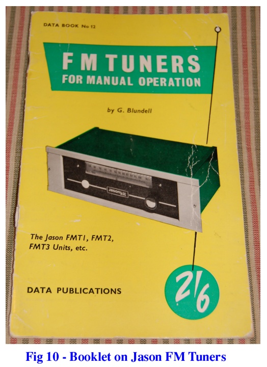
The most popular of such kits in the UK were those sold by Jason. These included fringe area and standard versions, switched or manual tuning, and with or without built in power supplies (most amplifiers of the period had sufficient spare power available to feed a tuner).
Once multiplexed stereo FM broadcasts began, there was a call for add-on decoders to convert existing mono tuners. A late example of a simple DIY solution to this was the article by A C Ainslie in Hi Fi News of February 1975, which used an MC1310P I/C. Since stereo required a higher signal level in order to obtain sufficient quieting, DIY articles also appeared on aerial construction, and on signal boosters such as D A Hendon’s in the May 1973 issue of Hi Fi News. Naturally, there were also designs for the construction of complete Stereo FM tuners, such as that by L Nelson-Jones in the April and May 1971 issues of Wireless World. This was a sophisticated unit, using a MOSFET front-end, I/C amplifiers in the IF stages, and ceramic resonators.
Improving TV sound was another area of interest to hi-fi enthusiasts. Various means of achieving this were discussed in an article by A Robertson in the April 1977 issue of Hi Fi News, including a DIY design for an optically-coupled isolator to take the sound signal from a TV set and safely feed it into a hi-fi system. Another DIY approach was described by A Ramsay in Hi Fi News of April 1974, using a UHF TV tuner head modified to give an RF output of 100MHz which could be fed to a normal FM radio tuned to that frequency.
Digital
The complexity of the electro- mechanical and electronic parts of digital music sources inevitably limited the possibility of DIY construction. However in the early days of Compact Disc, several articles were published which showed how commercially produced equipment could be modified to improve sound quality. Three pieces in Hi Fi News of December 1984 on “Sweetening CD Sound” dealt with various issues, including the 11 microsecond delay between channels caused by the use of a single DAC chip (common in the first players). In the June 1987 edition of Hi Fi News, M Norton wrote an article entitled “Building a Better CD Player” describing how he had extensively modified a Philips CD 104. Ben Duncan’s articles on “Supertuning CD” in the November and December 1987 issues of Hi Fi News, explained how to upgrade the analogue output stages of the Marantz CD450 and similar Marantz/Philips players. But one of the most ambitious DIY digital projects to appear was that in the Sept and Oct 1990 issues of Hi Fi News, again by Mr Duncan, on building complete DACs with either a Bitstream or Multibit approach.
Other Audio Electronics
Over the years there have been numerous other audio-related DIY projects to build. These have included designs for dedicated headphone amplifiers (eg Ben Duncan, Hi Fi News May 1997), and for various types of tone control (eg Reg Williamson’s Octave Graphic Equaliser, Hi Fi News August 1973, and Barry Porter’s Paragraph Parametric Equaliser, Electronics Today International February 1985). Other examples of potentially useful items for home construction included John Linsley-Hood’s design for a peak level indicator in the October 1980 issue of Hi Fi News, Ivor Humphries’ simple phase inverter in the November 1980 issue for those wishing to experiment with absolute phase, and a versatile four-way line level active crossover design by Ben Duncan carried in the February to May 1981 issues. Mains conditioners have been another area of DIY interest: eg Ben Duncan’s Pure Power designs in Hi Fi News (January 1998) and one by Paul Chappell in Electronics Today International of January 1988. When surround-sound and quadrophonics were in vogue, there were DIY projects on matrix decoders to build – eg S Hutton in Hi Fi News of November1973.
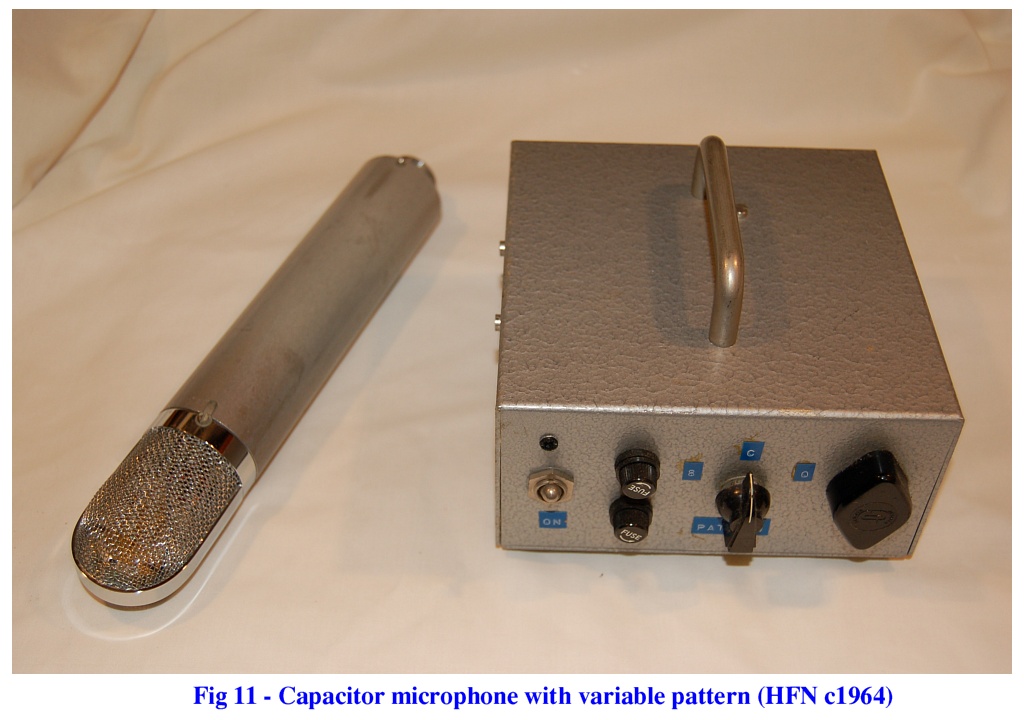
As well as these projects intended for domestic hi-fi systems, there were also those aimed more at the amateur recording fraternity. Several designs for sound mixers appeared (eg Wireless World May 1971, Elektor April-June 1986), and for studio equipment such as limiters, compressors and gates (eg Electronics Today International May 1983 and February 1989). There was certainly at least one piece on making one’s own electrostatic headphones and the electronics to go with them (Wireless World, November 1971), and there were even articles by people who had built their own capacitor microphones.
Test instruments
Although it was possible to build a DIY hi fi project without much more than a soldering iron and perhaps a simple multimeter, the keen constructor certainly found it desirable to have recourse to the appropriate test-gear. Sometimes it was possible to borrow or have access to the necessary instruments owned by one’s school, college, or employer, but many were not so lucky and commercially available equipment tended to be very expensive. Hence there was a demand for DIY designs which could be constructed at low cost.
A simple AF signal generator was a useful tool which could be readily built at little expense, particularly with the advent of solid state circuitry. One of the earliest such designs was contained in Mullard’s 1961 “Manual of Transistor Circuits” which was a Wien Bridge sine wave oscillator covering the whole audio bandwidth, and using a sensitive thermistor to control feedback round the three-transistor amplifier. Many similar designs followed, often using an I/C rather than discrete devices - for example those by P F Ridler in the August 1967 issue of Wireless World, and by John Linsley-Hood in the March 1975 issue of Hi Fi News. Maplin Electronics sold a popular kit, which like Mr Linsley-Hood’s design, included a Schmitt Trigger sine-to-square wave converter so that both waveforms were available. Another approach was to use the 8038 function generator I/C, which could produce sine, square and triangular waveforms: M Meakin’s design in the November 1985 issue of Electronics Today International was one which used this chip.
After a signal generator, probably the most useful piece of test-gear was an AC millivoltmeter. Together with a signal generator, this could be used to measure sensitivity, gain, output level, and frequency response, as well as setting up the correct bias level on a tape machine. In the 1960s Heathkit sold a millivoltmeter kit, using a single valve and mains powered, which worked very well and did not cost a great deal. Subsequently, several transistor or I/C based DIY designs were published, such as that by A J Ewins in Wireless World of December 1970, and by John Linsley-Hood in the April 1975 issue of Hi Fi News.
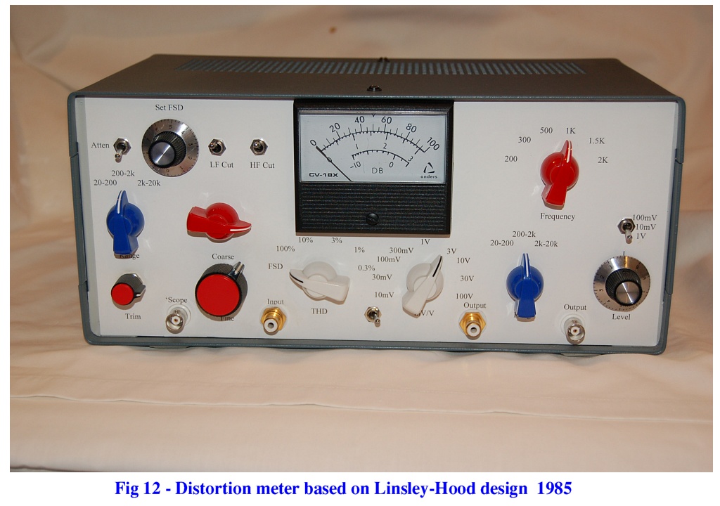
Another instrument which could be constructed without too much difficulty or expense was a meter to measure total harmonic distortion. This typically consisted of a low distortion sine-wave generator, a sharp-notch filter to remove the fundamental, and a millivoltmeter to compare the level of the residual after filtering with that of the original signal. Further useful information could be obtained if an oscilloscope was available by looking at the waveform of the residual. One such DIY project was that by John Linsley-Hood in the January-March 1985 issues of Electronics Today International, which was rather more ambitious than a simpler design he had published in the June 1975 issue of Hi Fi News.
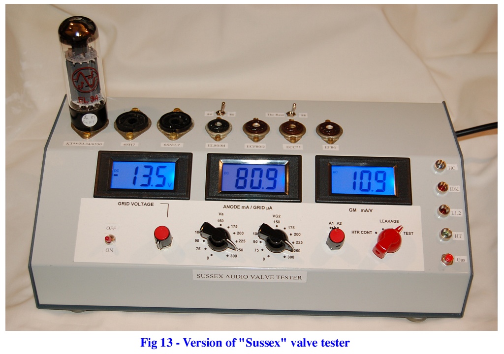
For those constructing or owning commercially produced valved equipment, the ability to test valves is of particular interest. However DIY designs for valve-testers seem to have been few and far between. Somewhat paradoxically, one of the most effective was published as recently as 2009 by Mike Rowe on the UK Vintage Radio website, since when many versions of his “Sussex” design have evidently been built.
In Conclusion
The foregoing accounts show clearly how big a role DIY played in the UK hi-fi scene during the latter part of the twentieth century. What is rather less apparent is quite why it has declined so markedly since the millennium.
Cost saving by doing-it-yourself is still possible in some areas, but it is seemingly not the driver it once was. It is true that on average Britons are much better off materially than they were in the early days of hi-fi, which suggests that more people can now afford to buy commercially produced equipment. Presumably there must still be many impecunious (young?) music-lovers who would find it economically worthwhile to construct their own loudspeakers and/or amplifier, yet this does not seem to be happening on any scale. Another factor may be that there is a huge pool of quality pre-owned equipment available nowadays, so that a good system can be assembled at reasonable cost without indulging in DIY.
So it seems likely that those who still make their own equipment do so mainly in order to experiment or customise the item they are constructing, or to make something which isn’t commercially available, rather than to save money as the principal objective. No doubt there also remains a small section of the hi-fi community which builds simply for enjoyment, and for the pride and satisfaction at producing something which works. And there does seem to be a growing interest in antique equipment, which often needs the skills acquired through DIY activities in order to service, repair and refurbish it.
David Lord.
19 June 2017
Appendix: Present day sources for components, spares and kits in the UK.
Modern standard components:
The following provide a good, fast service and stock a wide range:
RS Components (www.uk.rs-online.com)
Rapid Electronics (www.rapidonline.com)
Farnell (www.uk.farnell.com)
NB Farnell sells aluminium chasses suitable for building valve amps from scratch, which can be difficult to find elsewhere. Maplin still sells components, but their range is nowadays very limited.
Obsolete semiconductor devices:
These can be difficult to come by in small quantities, but Little Diode (www.littlediode.com) is a firm which seems to specialise in such items – admittedly at rather high cost.
Transformers:
For all types, including those for valve amps, E A Sowter (www.sowter.com) is a good UK source for quality items. Radford Revival (www.radfordrevival .co.uk) supply the transformers for Radford designs.
Audio Valves:
There are several UK companies, such as Billington (www.tube-and-valve-electronics.co.uk) and Chelmer Valve Company (www.chelmervalve.com). Hotrox (www.hotroxuk.com) is a good source of power valves at reasonable cost, and they like Billington and CVC provide a good service.
Loudspeaker kits and components:
Wilmslow Audio (www.wilmslow-audio.co.uk)
Falcon Acoustics (www.falconacoustics.co.uk)
IPL Acoustics (www.iplacoustics.co.uk)
Valve amp kits/components/finished items:
Audionote (www.audionote.co.uk)
World Audio Designs (www.world-designs.co.uk)
Radford Revival (www.radfordrevival.co.uk)
Spare parts:
These can sometimes be obtained from the manufacturer (if still in existence) or from refurbishers of vintage gear such as Geoff Kremer of ServiceSound (www.servicesound.com) who specialises in Ferrograph and Brenell tape machines. Turntable World (www.turntableworld.co.uk) is one company which carries record player spares, such as drive belts.
Finally, ebay is always worth trying for anything.
Main AudioDocs page